5
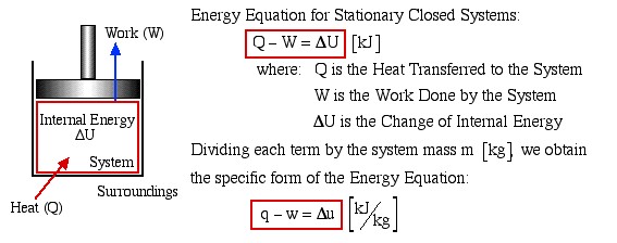
We consider the First Law of Thermodynamics applied to stationary closed systems as a conservation of energy principle. Thus energy is transferred between the system and the surroundings in the form of heat and work, resulting in a change of internal energy of the system. Internal energy change can be considered as a measure of molecular activity associated with change of phase or temperature of the system and the energy equation is represented as follows:
Energy Equation for Stationary Closed Systems
![]()
Dividing each term by the system mass m [kg] we obtain the specific form of the Energy Equation:
![]()
Heat [Q]
Energy transferred across the boundary of a system in the form of heat always results from a difference in temperature between the system and its immediate surroundings. We will not consider the mode of heat transfer, whether by conduction, convection or radiation, thus the quantity of heat transferred during any process will either be specified or evaluated as the unknown of the energy equation. By convention, positive heat is that transferred from the surroundings to the system, resulting in an increase in internal energy of the system.
Work [W]
In this course we consider three modes of work transfer across the boundary of a system, as shown in the following diagram:
Three forms of Work considered:
a) Boundary Work ![]() Piston – Cylinder
Piston – Cylinder
b) Shaft Work ![]() Paddle Wheel
Paddle Wheel
c) Electrical Work ![]() Volts
Volts ![]() (Amps)
(Amps) ![]() time
time
In this course we are primarily concerned with Boundary Work due to compression or expansion of a system in a piston-cylinder device as shown above. In all cases we assume a perfect seal (no mass flow in or out of the system), no loss due to friction, and quasi-equilibrium processes in that for each incremental movement of the piston equilibrium conditions are maintained. By convention positive work is that done by the system on the surroundings, and negative work is that done by the surroundings on the system, Thus since negative work results in an increase in internal energy of the system, this explains the negative sign in the above energy equation.
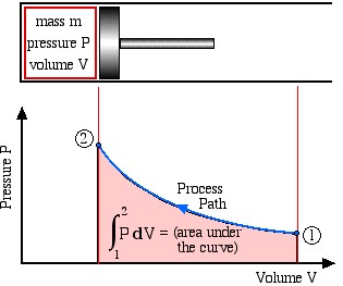
Boundary work is evaluated by integrating the force F multiplied by the incremental distance moved dx between an initial state (1) to a final state (2). We normally deal with a piston-cylinder device, thus the force can be replaced by the piston area A multiplied by the pressure P, allowing us to replace Adx by the change in volume dV, as follows:
![]()
This is shown in the following schematic diagram, where we recall that integration can be represented by the area under the curve.
![]() (area under the curve)
(area under the curve)
Note that work done is a Path Function and not a property, thus it is dependent on the process path between the initial and final states. Recall in Chapter 1 that we introduced some typical process paths of interest:
- Isothermal(constant temperature process)
- Isochoric or Isometric(constant volume process)
- Isobaric (constant pressure process)
- Adiabatic (no heat flow to or from the system during the process)
It is sometimes convenient to evaluate the specific work done which can be represented by a P-v diagram thus if the mass of the system is m [kg] we have finally:
![]()
where: P is pressure [kPa], V is volume [m3]
m is mass[kg],v is specific volume ![]()
W is work done [kJ], w is specific work done ![]()
We note that work done by the system on the surroundings (expansion process) is positive, and that done on the system by the surroundings (compression process) is negative.
Finally for a closed system Shaft Work (due to a paddle wheel) and Electrical Work (due to a voltage applied to an electrical resistor or motor driving a paddle wheel) will always be negative (work done on the system). Positive forms of shaft work, such as that due to a turbine, will be considered in Chapter 4 when we discuss open systems.
Internal Energy [u]
The third component of our Closed System Energy Equation is the change of internal energy resulting from the transfer of heat or work. Since specific internal energy is a property of the system, it is usually presented in the Property Tables such as in the Steam Tables.
Enthalpy [h]
In the case studies that follow we find that one of the major applications of the closed system energy equation is in heat engine processes in which the system is approximated by an ideal gas, thus we will develop relations to determine the internal energy for an ideal gas. We will find also that a new property called Enthalpy will be useful both for Closed Systems and in particular for Open Systems, such as the components of steam power plants or refrigeration systems. Enthalpy is not a fundamental property, however is a combination of properties and is defined as follows:
Enthalpy [kJ]: ![]()
Specific Enthalpy ![]() :
: ![]()
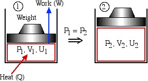
As an example of its usage in closed systems, consider the following constant pressure process:
![]()
![]()
![]()
Applying the energy equation we obtain: ![]()
However, since the pressure is constant throughout the process:
![]()
Substituting in the energy equation and simplifying:
![]()
![]() (constant pressure process)
(constant pressure process)
Values for specific internal energy (u) and specific enthalpy (h) are available from the Steam Tables, however for ideal gasses it is necessary to develop equations for Δu and Δh in terms of Specific Heat Capacities. We develop these equations in terms of the differential form of the energy equation in the next section of this chapter (Specific Heat Capacities of an Ideal Gas).
Solved Example
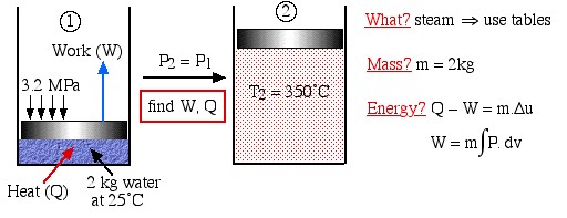
Two kilograms of water at 25°C are placed in a piston cylinder device under 3.2 MPa pressure as shown in the diagram (State (1)). Heat is added to the water at constant pressure until the temperature of the steam reaches 350°C (State (2)). Determine the work done by the fluid (W) and heat transferred to the fluid (Q) during this process using the energy equations, then compare this value of Q to that obtained from the change in enthalpy of the system.
Solution Approach:
We first draw the diagram of the process including all the relevant data as follows:
![]()
![]()
What?
![]()
Mass?
![]()
Energy?
![]()
![]()
Notice the four questions to the right of the diagram, which we should always ask before attempting to solve any thermodynamic problem. What are we dealing with – liquid? pure fluid, such as steam or refrigerant? ideal gas? In this case it is steam, thus we will use the steam tables to determine the various properties at the various states. Is the mass or volume given? If so we will specify and evaluate the energy equation in kiloJoules rather than specific quantities ![]() .
.
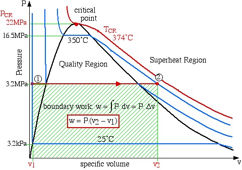
Since work involves the integral of Pdv we find it convenient to sketch the P-v diagram of the problem as follows:
boundary work ![]()
![]()
Notice on the P-v diagram how we determine the specific work done as the area under the process curve. We also notice that in the Compressed Liquid region the constant temperature line is essentially vertical. Thus all the property values at State (1) (compressed liquid at 25°C) can be determined from the saturated liquid table values at 25°C.
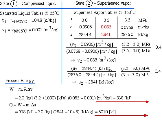
State (1) – Compressed liquid
![]()
![]()
State (2) – Superheated vapor
![]()
![]()
![]()
![]()
Process Energy
![Rendered by QuickLaTeX.com \begin{align*} W &= m \cdot P \cdot \Delta v\\ &= 2.0 \left[\si\kg\right] (3.2 \ast 1000) \left[\si\kPa\right] (0.085-0.001) \left[\si\m^3/\si\kg\right] = 538 \left[\si\kJ\right]\\ Q&=W+m\cdot \Delta u\\ &= 538\left[\si\kJ\right] + 2.0 \left[\si\kg\right] (2841-104.8) \left[\si\kJ/\si\kg\right]=6010 \left[\si\kJ\right] \end{align*}](https://pressbooks.pub/app/uploads/quicklatex/quicklatex.com-5f3794db5b28d1df118b00d1a541d201_l3.png)
Now to compare this value with that obtained using the change in enthalpy. From the steam tables we obtain the specific enthalpy values for the water (104.8 ![]() ) and for the steam (3110.45
) and for the steam (3110.45 ![]() ). We then multiply the difference of these two values by 2kg to get our solution:
). We then multiply the difference of these two values by 2kg to get our solution:
![]()
Specific Heat Capacities of an Ideal Gas
![]()
![]()
![]()
(1) ![]()
For a simple system, internal energy (u) is a function of two independent variables, thus we assume it to be a function of temperature T and specific volume v, hence:
![]()
Substituting equation (2) in the energy equation (1) and simplifying, we obtain:
![]()
Now for a constant volume process (dv = 0):
![]()
where: Cv is the specific constant volume heat capacity
That is, the specific constant volume heat capacity of a system is a function only of its internal energy and temperature. Now in his classic experiment of 1843 Joule showed that the internal energy of an ideal gas is a function of temperature only, and not of pressure or specific volume. Thus for an ideal gas the partial derivatives can be replaced by ordinary derivatives, and the change in internal energy can be expressed as:
![]()
Consider now the enthalpy. By definition h = u + Pv, thus differentiating we obtain:
![]()
![]()
Again for a simple system, enthalpy (h) is a function of two independent variables, thus we assume it to be a function of temperature T and pressure P, hence:
![]()
Substituting equation (6) in the energy equation (5), and simplifying:
![]()
Hence for a constant pressure process, since dP = 0:
![]()
where: Cp is the specific constant pressure heat capacity
That is, the specific constant pressure heat capacity of a system is a function only of its enthalpy and temperature. Now by definition:
![]()
Now since for an ideal gas Joule showed that internal energy is a function of temperature only, it follows from the above equation that enthalpy is a function of temperature only. Thus for an ideal gas the partial derivatives can be replaced by ordinary derivatives, and the differential changes in enthalpy can be expressed as:
![]()
Finally, from the definition of enthalpy for an ideal gas we have:
![]()
![]()
Define: ![]() (ratio of specific heat capacities)
(ratio of specific heat capacities)
Values of R, CP, Cv and k for ideal gases are presented (at 300K) in the table on Properties of Various Ideal Gases. Note that the values of CP, Cv and k are constant with temperature only for mon-atomic gases such as helium and argon. For all other gases their temperature dependence can be considerable and needs to be considered. We find it convenient to express this dependence in tabular form and have provided a table of Specific Heat Capacities of Air.
The Stirling Cycle Engine
Conceptually the Stirling engine is the simplest of all heat engines. It has no valves, and includes an externally heated space and an externally cooled space. It was invented by Robert Stirling, and an interesting website by Bob Sier includes a photograph of Robert Stirling, his original patent drawing of 1816, and an animated model of Stirling’s original engine.
In its original single cylinder form the working gas (typically air or helium) is sealed within its cylinders by the piston and shuttled between the hot and cold spaces by a displacer. The linkage driving the piston and displacer will move them such that the gas will compress while it is mainly in the cool compression space and expand while in the hot expansion space. This is clearly illustrated in the adjacent animation which was produced by Richard Wheeler (Zephyris) of Wikipedia.
Refer also to the animation produced by Matt Keveney in his Stirling engine animation website. Since the gas is at a higher temperature, and therefore pressure, during its expansion than during its compression, more power is produced during expansion than is reabsorbed during compression, and this net excess power is the useful output of the engine. Note that there are no valves or intermittent combustion, which is the major source of noise in an internal combustion engine. The same working gas is used over and over again, making the Stirling engine a sealed, closed cycle system. All that is added to the system is steady high temperature heat, and all that is removed from the system is low temperature (waste) heat and mechanical power.
Athens, Ohio, is a hotbed of Stirling cycle machine activity, both engines and coolers, and includes R&D and manufacturing companies as well as internationally recognized consultants in the area of Stirling cycle computer analysis. The parent company of this activity is Sunpower, Inc. It was formed by William Beale in the early 1970’s, mainly based on his invention of the free-piston Stirling engine which we describe below. Update (Jan. 2013): Sunpower was recently acquired by AMETEK, Inc. in Pensylvania, however continues doing Stirling cycle machine development in Athens, Ohio. Update (Nov. 2013): Sunpower has recently introduced a 1 kW Stirling Developers Kit based on a free piston Stirling engine fired by Propane or natural gas.
Some examples of single cylinder Stirling engines: Stirling Technology Inc. is a spinoff of Sunpower, and was formed in order to continue the development and manufacture of the 5 kW ST-5 Air engine. This large single cylinder engine burns biomass fuel (such as sawdust pellets or rice husks) and can function as a cogeneration unit in rural areas. It is not a free-piston engine, and uses a bell crank mechanism to obtain the correct displacer phasing. Another important early Stirling engine is Lehmann’s machine on which Gusav Schmidt did the first reasonable analysis of Stirling engines in 1871. Andy Ross of Columbus, Ohio built a small working replica of the Lehmann machine, as well as a model air engine.
Solar Heat and Power Cogeneration: With the current energy and global warming crises, there is renewed interest in renewable energy systems, such as wind and solar energy, and distributed heat and power cogeneration systems. Cool Energy, Inc. of Boulder, Colorado, is currently in advanced stages of developing a complete solar heat and power cogeneration system for home usage incorporating Stirling engine technology for electricity generation. This unique application includes evacuated tube solar thermal collectors, thermal storage, hot water and space heaters, and a Stirling engine/generator.
Ideal Analysis: Please note that the following analysis of Stirling cycle engines is ideal, and is intended only as an example of First Law Analysis of closed systems. In the real world we cannot expect actual machines to perform any better than 40 – 50% of the ideal machine. The analysis of actual Stirling cycle machines is extremely complex and requires sophisticated computer analysis (see for example the course notes on: Stirling Cycle Machine Analysis.)
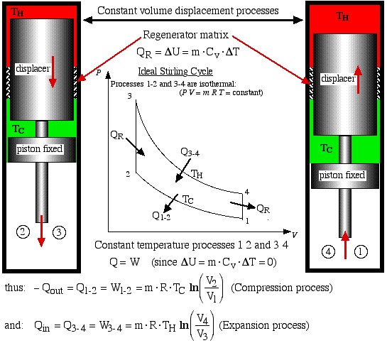
The free-piston Stirling engine developed by Sunpower, Inc is unique in that there is no mechanical connection between the piston and the displacer, thus the correct phasing between them occurs by use of gas pressure and spring forces. Electrical power is removed from the engine by permanent magnets attached to the piston driving a linear alternator. Basically the ideal Stirling engine undergoes 4 distinct processes, each one of which can be separately analyzed, as shown in the P-V diagram below. We consider first the work done during all four processes.
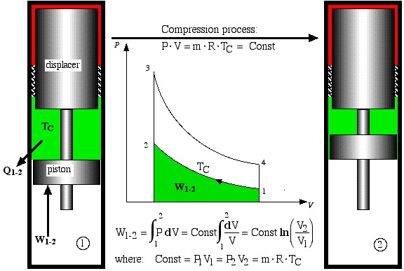
- Process 1-2 is the compression process in which the gas is compressed by the piston while the displacer is at the top of the cylinder. Thus during this process the gas is cooled in order to maintain a constant temperature TC. Work W1-2 required to compress the gas is shown as the area under the P-V curve, and is evaluated as follows.
Compression process
![]()
![]()
![]()
![]()
![]()
![]()
- Process 2-3 is a constant volume displacement process in which the gas is displaced from the cold space to the hot expansion space. No work is done, however as we shall see below, a significant amount of heat QR is absorbed by the gas from the regenerator matrix.
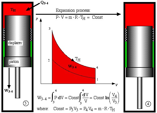
- Process 3-4 is the isothermal expansion process. Work W3-4 is done by the system and is shown as the area under the P-V diagram, while heat Q3-4 is added to the system from the heat source, maintaining the gas at a constant temperature TH.
Expansion process
![]()
![]()
![]()
![]()
![]()
- Finally, process 4-1 is a constant volume displacement process which completes the cycle. Once again we will see below that heat QR is rejected by the working gas to the regenerator matrix.
The net work, Wnet, done over the cycle is given by: Wnet = (W3-4 + W1-2), where the compression work W1-2 is negative (work done on the system).
We now consider the heat transferred during all four processes, which will allow us to evaluate the thermal efficiency of the ideal Stirling engine. Recall from the previous section that in order to do a First Law analysis of an ideal gas to determine the heat transferred we needed to develop equations to determine the internal energy change Δu in terms of the Specific Heat Capacities of an Ideal Gas.
The two constant volume processes are formed by holding the piston in a fixed position, and shuttling the gas between the hot and cold spaces by means of the displacer. During process 4-1 the hot gas gives up its heat QR by passing through a regenerator matrix, which is subsequently completely recovered during the process 2-3.
![]()
![]()
![]()
![]()
Constant processes 1 2 and 3 4
![]()
![]()
![]()
Now from the First Law for a cycle:
![]()
Thus thermal efficiency:
![]()
Note that: ![]() thus we find that:
thus we find that:
![]()
We will find in Chapter 5 that this is the maximum theoretical efficiency that is achievable from a heat engine, and usually referred to as the Carnot efficiency.
Note that if no regenerator is present the heat QR must be supplied by the heater. Thus the efficiency will be significantly reduced to ![]() . Furthermore the cooler will then have to reject the heat that is normally absorbed by the regenerator, thus the cooling load will be increased to Qout + QR. Recall that Q2-3 = QR = -Q4-1.
. Furthermore the cooler will then have to reject the heat that is normally absorbed by the regenerator, thus the cooling load will be increased to Qout + QR. Recall that Q2-3 = QR = -Q4-1.
Note that the practical Stirling cycle has many losses associated with it and does not really involve isothermal processes, nor ideal regeneration. Furthermore since the Free-Piston Stirling cycle machines involve sinusoidal motion, the P-V diagram has an oval shape, rather than the sharp edges defined in the above diagrams. Nevertheless we use the ideal Stirling cycle to get an initial understanding and appreciation of the cycle performance.
The Stirling Cycle Cooler
One important aspect of Stirling cycle machines that we need to consider is that the cycle can be reversed – if we put net work into the cycle then it can be used to pump heat from a low temperature source to a high temperature sink. Sunpower, Inc. has been actively involved in the development of Stirling cycle refrigeration systems and produces Stirling cycle cryogenic coolers for liquefying oxygen. In 1984 Sunpower developed a free piston Duplex Stirling Machine having only three moving parts including one piston and two displacers, in which a gas fired Stirling cycle engine powered a Stirling cycle cooler. Global Cooling, Inc. was established in 1995 as a spinoff of Sunpower, and was formed mainly in order to develop free-piston Stirling cycle coolers for home refrigerator applications. These systems, apart from being significantly more efficient than regular vapor-compression refrigerators, have the added advantage of being compact, portable units using helium as the working fluid (and not the HFC refrigerants such as R134a, having a Global Warming Potential of 1,300). More recently Global Cooling decided to concentrate their development efforts on systems in which there are virtually no competitive systems – cooling between -40°C and -80°C, and they established a new company name: Stirling Ultracold.
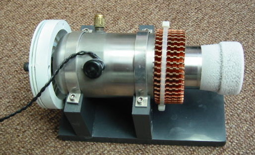
We are fortunate to have obtained two original M100B coolers from Global Cooling. The one is used as a demonstrator unit, and is shown in operation in the following photograph. The second unit is set up as a ME Senior Lab project in which we evaluate the actual performance of the machine under various specified loads and temperatures.
The Air-Standard Diesel Cycle (Compression-Ignition) Engine
The Air Standard Diesel cycle is the ideal cycle for Compression-Ignition (CI) reciprocating engines, first proposed by Rudolph Diesel over 100 years ago. The following link by the Kruse Technology Partnership describes the four-stroke diesel cycle operation including a short history of Rudolf Diesel. The four-stroke diesel engine is usually used in motor vehicle systems, whereas larger marine systems usually use the two-stroke diesel cycle. Once again we have an excellent animation produced by Matt Keveney presenting the operation of the four-stroke diesel cycle.
The actual CI cycle is extremely complex, thus in initial analysis we use an ideal “air-standard” assumption, in which the working fluid is a fixed mass of air undergoing the complete cycle which is treated throughout as an ideal gas. All processes are ideal, combustion is replaced by heat addition to the air, and exhaust is replaced by a heat rejection process which restores the air to the initial state.
The ideal air-standard diesel engine undergoes 4 distinct processes, each one of which can be separately analyzed, as shown in the P-V diagrams below. Two of the four processes of the cycle are adiabatic processes (adiabatic = no transfer of heat), thus before we can continue we need to develop equations for an ideal gas adiabatic process as follows:
The Adiabatic Process of an Ideal Gas (Q=0)
The analysis results in the following three general forms representing an adiabatic process:
![]()
where k is the ratio of heat capacities and has a nominal value of 1.4 at 300K for air.
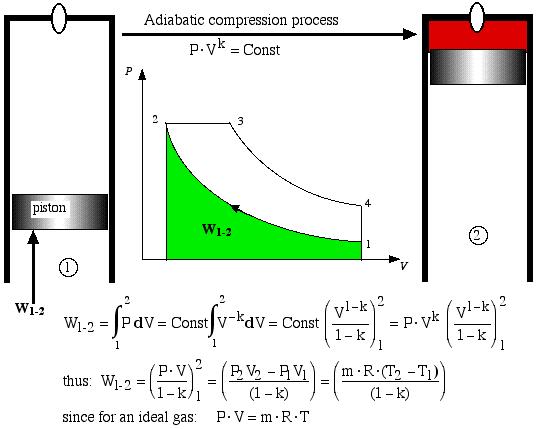
Process 1-2 is the adiabatic compression process. Thus the temperature of the air increases during the compression process, and with a large compression ratio (usually > 16:1) it will reach the ignition temperature of the injected fuel. Thus given the conditions at state 1 and the compression ratio of the engine, in order to determine the pressure and temperature at state 2 (at the end of the adiabatic compression process) we have:
![]()
![]()
Work W1-2 required to compress the gas is shown as the area under the P-V curve, and is evaluated as follows.
Adiabatic compression process
![]()
![]()

![]()
![]()
An alternative approach using the energy equation takes advantage of the adiabatic process (Q1-2 = 0) results in a much simpler process:
![]()
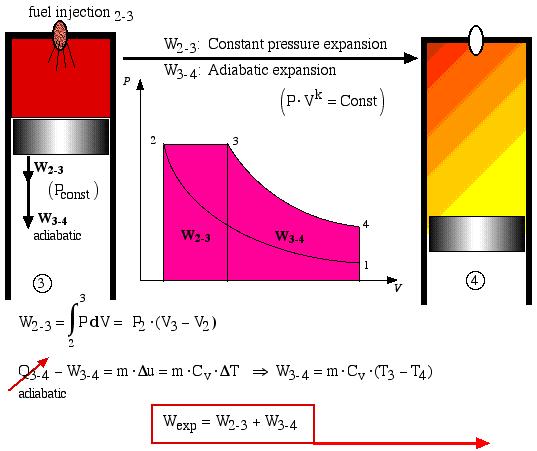
During process 2-3 the fuel is injected and combusted and this is represented by a constant pressure expansion process. At state 3 (“fuel cutoff”) the expansion process continues adiabatically with the temperature decreasing until the expansion is complete.
Process 3-4 is thus the adiabatic expansion process. The total expansion work is Wexp = (W2-3 + W3-4) and is shown as the area under the P-V diagram and is analyzed as follows:
![]() : Constant pressure expansion
: Constant pressure expansion
![]() : Adiabatic expansion
: Adiabatic expansion
![]()
![]()
![]()
![]()
![]()
Finally, process 4-1 represents the constant volume heat rejection process. In an actual Diesel engine the gas is simply exhausted from the cylinder and a fresh charge of air is introduced.
The net work Wnet done over the cycle is given by: Wnet = (Wexp + W1-2), whereas before the compression work W1-2 is negative (work done on the system).
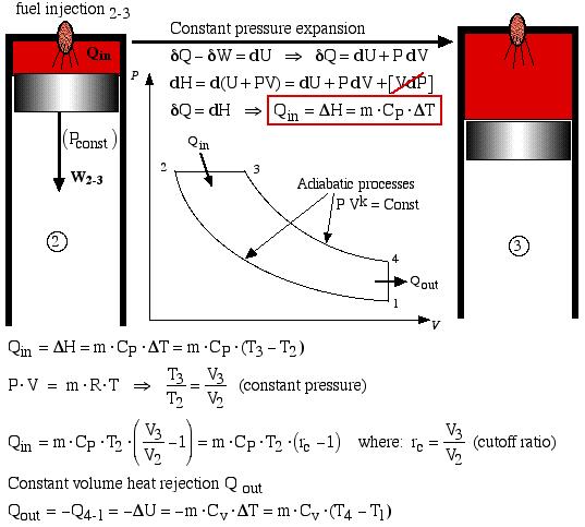
In the Air-Standard Diesel cycle engine the heat input Qin occurs by combusting the fuel which is injected in a controlled manner, ideally resulting in a constant pressure expansion process 2-3 as shown below. At maximum volume (bottom dead center) the burnt gasses are simply exhausted and replaced by a fresh charge of air. This is represented by the equivalent constant volume heat rejection process Qout = -Q4-1. Both processes are analyzed as follows:
Constant pressure expansion
![]()
![]()
![]()
![]()
![]()
![]()
![]()
![]()
![]()
![]()
![]()
![]()
![]()
At this stage we can conveniently determine the engine efficiency in terms of the heat flow as follows:
![]()
![]()
Again from the First Law for a cycle:
![]()
Thus thermal efficiency:![]()
The Air-Standard Otto Cycle (Spark-Ignition) Engine
The Air Standard Otto cycle is the ideal cycle for Spark-Ignition (SI) internal combustion engines, first proposed by Nikolaus Otto over 130 years ago, and which is currently used most motor vehicles. The following link by the Kruse Technology Partnership presents a description of the four-stroke Otto cycle operation including a short history of Nikolaus Otto. Once again we have excellent animations produced by Matt Keveney presenting both the four-stroke and the two-stroke spark-ignition internal combustion engine operation.
The analysis of the Otto cycle is very similar to that of the Diesel cycle which we analyzed in the previous section. We will use the ideal “air-standard” assumption in our analysis. Thus the working fluid is a fixed mass of air undergoing the complete cycle which is treated throughout as an ideal gas. All processes are ideal, combustion is replaced by heat addition to the air, and exhaust is replaced by a heat rejection process which restores the air to the initial state.
The most significant difference between the ideal Otto cycle and the ideal Diesel cycle is the method of igniting the fuel-air mixture. Recall that in the ideal Diesel cycle the extremely high compression ratio (around 18:1) allows the air to reach the ignition temperature of the fuel. The fuel is then injected such that the ignition process occurs at a constant pressure. In the ideal Otto cycle the fuel-air mixture is introduced during the induction stroke and compressed to a much lower compression ratio (around 8:1) and is then ignited by a spark. The combustion results in a sudden jump in pressure while the volume remains essentially constant. The continuation of the cycle including the expansion and exhaust processes are essentially identical to that of the ideal Diesel cycle.
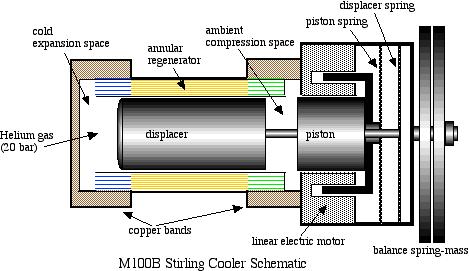
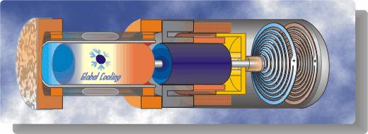
A schematic diagram followed by an animated schematic of the cooler (both courtesy of Global Cooling) are shown below:
Conceptually the cooler is an extremely simple device, consisting essentially of only two moving parts – a piston and a displacer. The displacer shuttles the working gas (helium) between the compression and expansion spaces. The phasing between the piston and displacer is such that when the most of the gas is in the ambient compression space then the piston compresses the gas while rejecting heat to the ambient. The displacer then displaces the gas through the regenerator to the cold expansion space, and then both displacer and piston allow the gas to expand in this space while absorbing heat at a low temperature.
